
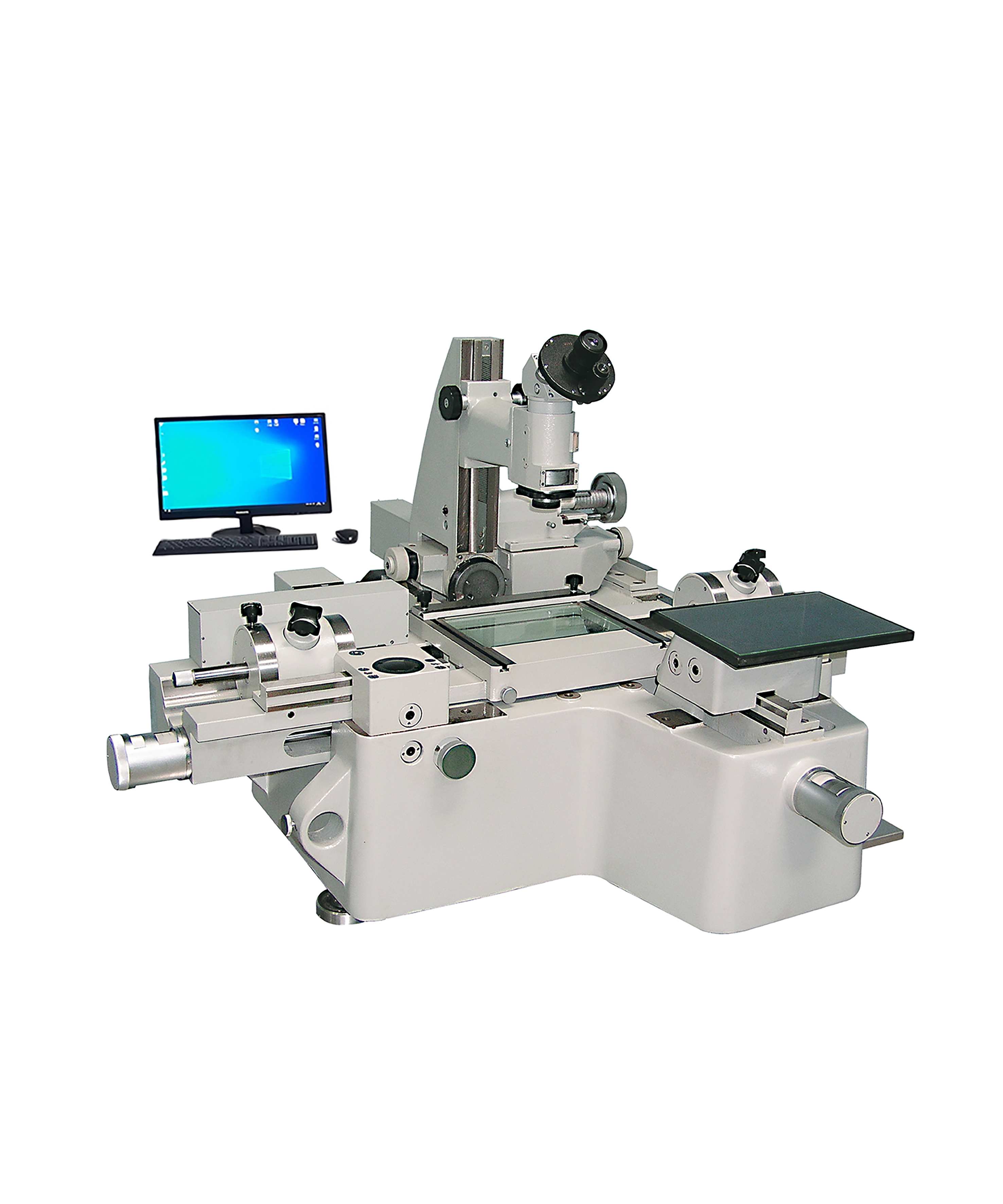
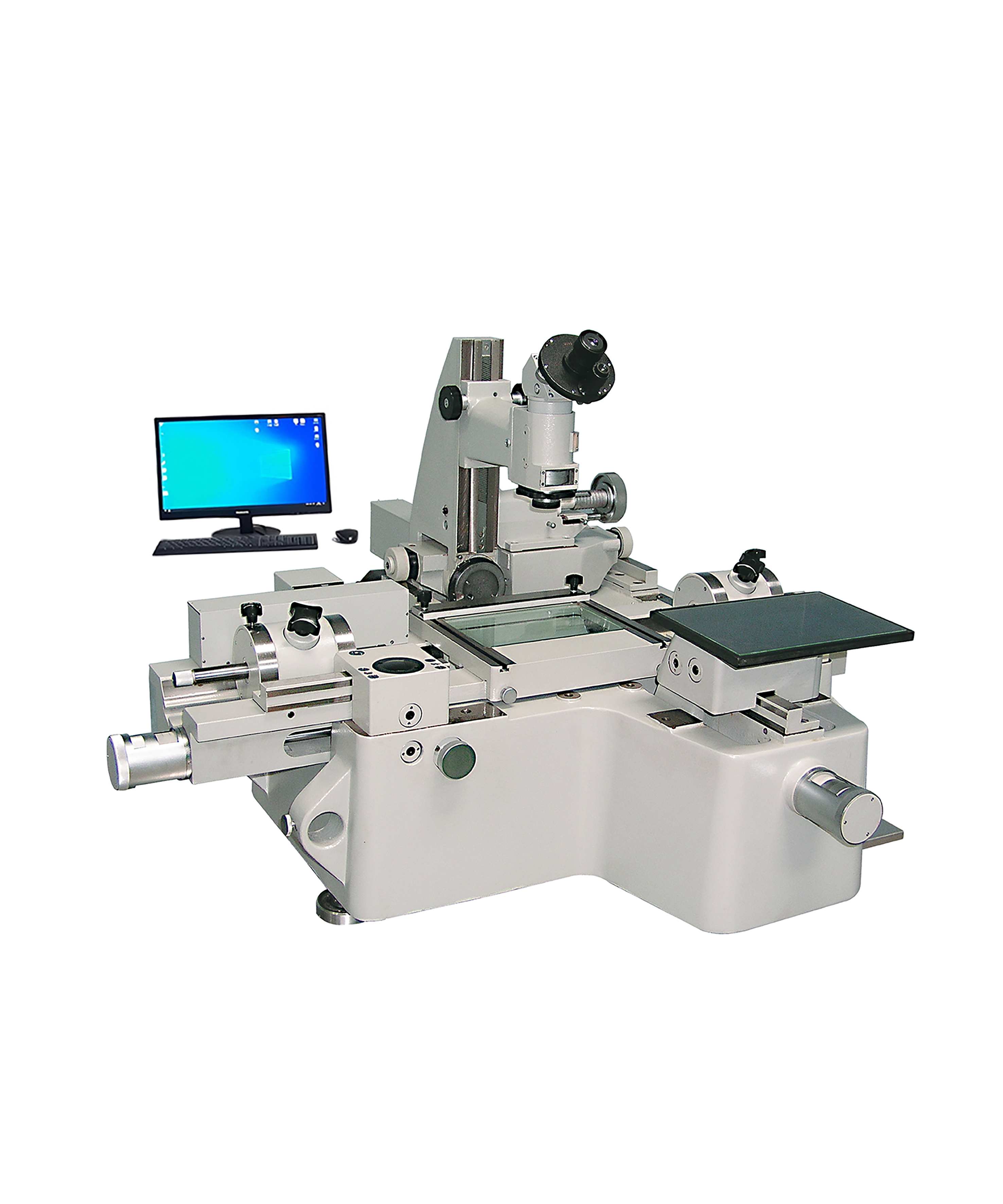
SPTM-13B Digital Universal Toolmaker's Microscope
Le microscope universel numérique SPTM-13B est un instrument de mesure de haute précision intégrant la technologie photoélectrique et numérique. Il mesure les paramètres du filetage externe, les spécifications des engrenages, les erreurs de forme et de localisation, ainsi que diverses pièces formées. Équipé de plusieurs oculaires/objectifs, d’une échelle de grillage de précision, d’une tête d’index d’affichage numérique (plage 0º~360°, résolution de 5") et d’un indicateur de position optique, il assure une détection précise. Doté de logiciels de mesure 2D (acquisition de données, construction, analyse de tolérances, échange de coordonnées) et de sortie de données vers AUTOCAD/EXCEL/WORD, il prend en charge des tâches complexes. Caractéristiques clés : plages X/Y 200/100 mm, résolution 0,0002mm, précision (1+L/100)μm, inclinaison ±12°, et éclairage halogène 24V 150W.
Détails du produit
Caractéristiques :
The master microscope is equipped with multiple eyepieces and objectives, with large view field and sharp imaging; The photoelectric and digital technology is adopted, taking the precision grating scale as sensory element, with high accuracy of measurement; Advanced computer processing technology is adopted to input collected real-time signals in the grating and video data system into the computer; which were processed by the powerful 2-coordinate measuring software, this instrument can effectively fulfill all kinds of complicated measuring work; The master microscope can out-beat left and right, suitable for the measurement of helical parts; The transmission and indirect lighting can measure profile and the surface sizes; High-speed movement and vernier arrangement are installed and can be switched over speedily; Multiple accessories of tailstock, V-type support, height-measuring device, etc. are equipped, with wide-range uses.
Le microscope Universal Toolmaker’s peut mesurer :
-Measuring the intermediate, coarse and minor-diameter, pitch, tooth-form semi-angle of the external screw-thread for screw-threads, leading screws, worms, etc.;
- Mesurer l’angle de plomb, de la forme de scie et l’angle du profil de la dent, de l’engrenage ;
- Mesurer les erreurs de chiffre et d’emplacement du degré de position sur la carte électronique, sur le gabarit de forage, ou sur la plaque d’ouverture, ainsi que celles de la symétrie sur la fente de clé, etc.
Mesurer différents types de pièces façonnées, par exemple, plaques d’échantillonnage, outil de tournage de forme, coupe-formage, matrice de poinçonnage, came, etc. ;
Paramètres techniques :
|
Modèle |
SPTM-13B |
|
Plage des coordonnées X (mm) |
200 mm |
|
Plage des coordonnées Y (mm) |
100 mm |
|
Résolution : |
0.0002 (mm) |
|
Surface de la table de travail (mm) |
260x270mm |
|
Précision de l’instrument : |
(1+L/100)μm, |
|
Plage d’inclinaison : |
±12° |
|
Diamètre maximal tenu par la crosse arrière : |
φ100 mm |
|
Longueur maximale prise par la crosse arrière : |
700 mm |
|
Éclairage de transmission : |
24V 150W Halogen tungsten lamp |
|
Éclairage réfléchi : |
24V 150W Halogen tungsten lamp |
|
Tailles globales de l’instrument (mm) : |
1300×1250×800 |
|
Poids du mainframe : |
450 kg |
Objectif:
|
Grossissement objectif |
Grossissement total |
working distance (mm) |
Object field (mm) |
|
1X |
10X |
79 |
20 |
|
3X |
30X |
69 |
6.7 |
|
5X |
50X |
49 |
4 |
Tête d’index d’affichage numérique
Angle measuring range: 0º~360º
Resolution ratio of the angle measuring: 5″
Accuracy of the angle measuring: 30″
Indicateur de position optique
Minimum detection aperture: φ5 mm
Maximum detection depth: 15mm Metering force: 0.1N
Locating stability: 0.001mm
Limit error gauged for head diameter: 0.0005mm
Maximum load of the instrument: 40kg
Overall size of the principal machine of the instrument: (L×B×H) = 1300×1250×800
Weight of the principal machine of the instrument: 450kg
Environnement ambiant du service d’instrument :
Room temperature: 20℃±1°
Relative humidity: Not more than 60%
CD of 2-D imeasuring software
1. Acquisition functions: Acquire dots, lines, circulars and arcs
2. Construction functions: Construct the dots acquired to form the straight line, the circular and the arc
3. Combined computing functions:
The combination calculation between “dot” and “dot” gives their dot distance and midpoint coordinate;
The combination calculation between “dot and line” gives their dot line distance;
The combination calculation between “straight line and straight line for their crossing” gives their intersecting point coordinate and their included angle;
The combination calculation between “straight line and straight line for their centering” gives the central line information for the two lines;
The combination calculation between “circular and circular” gives the information of the crossing points and the center distance of the circulars; and
The combination calculation between “circular and straight” gives the information of their crossing points and the distance from the center of the circular to the line.
4. Functions for the treatment of the shape and location tolerance:
Mesure de la rondeur entre circulaire et arc ;
Mesure de la linéarité ;
Mesure de l’axialité ;
Mesure de la symétrie ; et
Mesure de la localisation.
5. Exchange of the coordinate system:
La transition de coordonnées entre la coordonnée rectangulaire et la coordonnée du pôle
Établissez la nouvelle coordonnée et remettez la coordonnée droite
6. Data output: Outputting to AUTOCAD, EXCEL AND WORD to conduct further data processing.
Obtenez un devis ou plus d’informations
Our technical experts are ready to help you configure the perfect testing solution for your specific requirements. Fill out the form and we'll get back to you within 2 hours.